Draft Cycle Works

Showing posts with label engine. Show all posts

Sunday, March 14, 2021

Survivor Chop: Clutch Repair

This one is short, but important.  When removing the clutch, you can use a pair of channel locks to keep the basket from rotating as you use the clutch nut tool to remove the nut.  Same for reinstallation. Just use the sides of the jaws to resist the rotation by placing them against the flat bosses next to the springs and pressure plate posts. Clutch nut torque is 33 - 36 ft-lb.  When removing or installing the pressure plate, be sure to tighten or loosen the 4 bolts evenly.  The pressure plate breaks easily when this is not followed.  I've only ever broken one... this one... out of many.  But I'm usually careful.  The proper torque for the pressure plate bolts is 6 - 7.5 ft-lb.

Removing clutch nut.

Ensure that the pressure plate bolts are evenly loosened or tightened.  When installing, make sure that the plate is moving down onto the clutch hub studs properly to avoid the bolt clamping down prematurely on the wrong surface and potentially leading you to snapping the pressure plate.


All steels should have the sharp edge facing inward or at least in the same direction.  I placed a v notch on each of the oiling holes in the clutch hub to aide with oil collection.  This is a tip from Hondaman that I did on my heavily built 836 in Rock Flute and there was slightly noticeable difference in the smoothness of the clutch.  Before doing this, the clutch was grabby and neutral was impossible to find. Cut the V groove so oil is funneled into the oiling holes.  I.e. on the left side of the holes when looking at the bottom of the inner side of the clutch hub.  The clutch rotates clockwise.

Clutch parts cleaned and inspected.  Note the v grooves in the hub at the top left. Not the prettiest work, but it seems to help.


Survivor Chop: Clean and Polish

This topic isn't exactly the most exciting, but it's very rewarding.  When this bike showed up, it was dirty, the chrome was pitted and flaking, and the paint looked dull.  It looked a lot better in pictures than in reality.  

Time to get to work, pulling it apart, scrubbing, polishing, waxing, and blistering.  For this, I'll be using, blue magic metal polish, Collonite 845 insulator wax, 0000 steel wool, microfiber cloths, plastic brushes, degreaser, carb cleaner, soap, and water.  I made a deal with a polisher to get a full set of engine covers polished in exchange for some spare covers for him to polish and sell.  It worked out great because, well, I hate polishing and have quite a few spare engine covers.

One thing to note that is very important.  If you have your engine covers polished, be sure to wash them thoroughly to remove any remaining rouge before putting them on your engine.  Rouge is abrasive and while it may seem insignificant, you don't want chunks of this stuff floating around in your oil.  also, while the covers are off, this is the best time to put a good coat of sealing wax on.  Enter Collonite 845.

This work was done quite a few months ago, but I haven't been able to keep up on the blog.  I was in between a surgeries to fix damaged nerves in my arms, so my Dad was helping out quite a bit.  And he continues to do so.   We basically scrubbed and polished everything we could. While tearing the bike down for cleaning, we inspected everything to ensure it was in good order, greased the greasy parts, and replaced all gaskets.  The rear wheel turned out surprisingly good, considering it's perceived condition when it arrived.  My Dad is obsessed with doing great work, and it shows.

Dad working on the rear wheel.

Bolting the sprocket to the carrier.

Piles of parts.

The pipes cleaned up nicely even though they still have some sort of acid drip markings on them.

Scrubbing every tiny bit.

Polished engine covers.

In the picture above, notice that the stator cover it dressed up with some black paint for accent.  This is a relatively simple job and I think it looks great.  Just roughly mask off the stator cover except the outer ring and the Honda logo, spray black and let dry to touch.  Once the paint is dry to touch, remove the tape and gently wipe away the paint on the side of the outer ring and the lettering with a solvent, leaving the background black.  I follow this by carefully polishing the exposed aluminum to minimize oxidation.

Unmasked and painted stator cover before wiping off the excess paint with solvent.

While removing excess paint, you may accidentally remove paint from the background.  Just dab a little paint on the bare spot to fill it back in.  Oops.

Finished product.

Once everything is cleaned, polished, greased, etc. it's time to throw it all back together.  I bought a stainless steel bolt kit for the engine and polished all of the heads.  When using stainless bolts on an aluminum block, consider using a dab of antiseize.  The contact between stainless steel and aluminum causes galvanic corrosion and can cause the bolts to bind up and make removing them in one piece difficult or impossible.  Its a little more work up front, but it's good insurance.  A little dab will do ya.

Polish, polish, polish.

Polish, polish, polish.

ANTISEIZE people!!!  I hate snapping these bolts off.  Also, 5 ft-lb of torque is the spec for most of the engine bolts.  You might need a little more to help it seal on worn surfaces, but be careful.  The antiseize will also help you get more torque without binding up the threads.

Here's a little before and after of the paint and polish process.

Before.

After.

More after.  So pretty.

Ok, one more.

I installed a few parts that John had given me, including that super shiny bread box air cleaner.  Thanks John!

It runs and rides now, but still needs more work.

Out for a little celebratory ride with my homey.

Now, onto more work. I still need to replace the front brake line and master cylinder, tune the carbs (they're way out...150s are a no-no for a stocker), make a plate cover for the instrument light cluster, etc. etc. etc.

Friday, May 22, 2020

Survivor Chop Engine Paint: Repainting an engine in the frame.


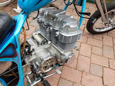
Grungy engine with a poor attempt at a black wrinkle paint top end.

One of the biggest issues with the cosmetics on this bike, aside from the slowly deteriorating retro paint job, is the engine.  The chrome covers are shot and a previous owner decided to make an attempt to paint the top end with black wrinkle paint.  I hate wrinkle paint.  Most of it is already flaking off like the chrome, but there's still plenty partially stuck all over those nice fins.  The bottom end paint has held up OK for 48 years.  It has the typical yellowed look.

To clean this engine up, I am going to repaint the top end in the frame, replace the engine covers with a polished set, and clean the bottom end up.  Aluminum Duplicolor enamel engine paint (DE1615) matches pretty closely to the factory gray, but the yellowing of the original paint will always make it look a bit different.  Other engines I've worked on had paint that didn't yellow as much, so sometimes repainting parts instead of the whole can work out better than this.

Materials I will be using to clean the engine include brake cleaner, simple green, carburetor cleaner, rubbing alcohol, water, 1/4" and 3/8" steel wire tube brushes, scuff pads, sand paper, screwdrivers, paper towels, and a drill. For painting and masking, I will be using Duplicolor engine enamel in Aluminum, painters tape, newspaper, drop cloths, and saran wrap.

The first step in repainting the top end while in the bike is to strip everything off the engine and get it out of the way.  I removed everything but the valve cover because it will be used to essentially mask off the cam area during painting.  Plug all the ports and entryways into the engine.  Next, I gave the bike a good rinse with a solvent.  I used Brakleen, which can sometimes discolor paint, so be careful.  Carburetor cleaner and brake cleaning solvents can damage paint, but I've used it many times to quickly degrease older paint.  The fins on these engines hold a lot of grime, so it's important to be thorough if you want your new paint to adhere.  I sprayed the engine down until the stream of solvent coming out of the fins was a very light brown, instead of the coffee color that it originally began with.

Once most of the grease had been washed away, it's time for a long scrubbing process.  Using steel wire brushes on aluminum can be pretty aggressive, so you may want to try brass brushes first and see if this will remove the loose paint.  Unfortunately the large chunks on this engine won't budge.  I cut the looped ends off the 3/8" tube brush and chucked it in the drill.  Beginning at a slow speed, move the tube brush in and around all of the fins, being sure to scrub every surface.  These tube brushes can make quick work of the debris between the fins.

3/8" wire tube brush getting acquainted with the engine.

Leave the handle long on the tube brush to allow for a long reach and some flex to get into difficult areas.

Continue to scrub every fin, top and bottom until only a light dust comes out.  Rinse with water and simple green as you go to keep the surfaces somewhat clean.  If you're using steel wire brushes, be careful not to scrub too long because you will leave deep scratch marks in the fins.  You'll then need some heavy coats of paint or some primer to level it out again. Once all of the fins have been scrubbed, go back over the outer edge with 240-320 grit sand paper or maybe just a scuff pad to knock off any loose paint that got missed by the brush. Be sure to sand and smooth the top part of the head very well because this is the most visible area.

Early stages of wire brushing the fins.

Cleaned fins ready for a lot of rinsing and further degreasing.

More cleaning/rinsing is needed because, while the wire brushes scraped away a lot of loose paint, it's inevitable that they also found many chunks of stubborn grease that have now been smeared across the metal. More brake cleaner can be used, but it can leave residue that will need to be removed before painting.  Carburetor cleaner does not leave a residue, but can damage paint, so use it carefully.  Other safer options are simple green or high proof alcohol.  Since I ran out of simple green, I'm using carburetor cleaner sparingly, followed by a full rinse in 91% rubbing alcohol.  

Every fin and surface will need to be wiped down with solvent.  To do this, I cut strips of paper towels and wrap them around the end of a flathead screwdriver that fits between the fins.  Spray generously with rubbing alcohol and replace the strips of paper towels until they come out mostly clean.  It's difficult to get everything out of the fins when working with the engine in the frame, but patience pays off.

Materials for cleaning before paint.
My shop apprentice applying the rubbing alcohol generously.

Strip of paper towel wrapped around a flathead screwdriver.

Once everything is clean, it's a good idea to degrease the surrounding materials so tape will adhere nicely when masking off for paint. Another good reason to use rubbing alcohol is that it dries quickly and wont leave hidden puddles that will prevent the paint from sticking.  When everything is clean and dry, it's time to start masking off for painting.  

I set my Duplicolor aluminum spray can out in partial shade so it can warm up while I mask off the top end.  This helps the paint flow and level better.  Just be careful because it will run easier.  You can also use an etching primer to aide with adhesion to bare metal.  I use this on many parts, but have had very good, consistent success with just spraying the Duplicolor engine enamel directly onto bare aluminum engine cases.  

For top end repainting, I mask off just below the base gasket so I can hide the edge of the paint job.  begin masking from the edges of the painted area outward. Then finish off by covering every surface to ensure no rogue paint particles haze up your trippy frame paint.  After taping off the edge near the base gasket, I tape newspaper over the lower edge of that tape and work outward.  After the engine is mostly covered, it's time for drop cloths and saran wrap for any odd protrusions like the turn signals.  When masking off to paint an engine in the frame, always consider the angles you need in order to properly coat the surfaces.  I tape off the down tubes to minimize the interference of the masking on how I can spray onto the fins.  

When everything is masked off, look at all the masked surfaces from every angle to ensure that it is all covered.  Now it's time for paint.  Shake your paint like mad.  If you're using an etching primer, follow the instructions and lightly mist the bare metal surfaces.  Let it dry and then move on to base coat.  Since I'm not using etching primer here, I'm ready for the color.  The first two coats should be light.  Dont try to saturate and get even coloring on the first two coats.  Spray at an upward angle to get the bottom of the fins and a downward angle for the top of the fins (about a 15 degree angle).  Let the paint dry for 5 to 10 minutes between coats depending on the temperature you are painting in.  After the first two coats, apply a medium coat.  Let this dry for a few minutes and then you can apply another coat if needed to level the surfaces a bit.

Top end masked off.

Top end painted and drying.

Look around to make sure it's even and completely painted.  Once satisfied, let it dry for at least an hour before removing the masking.  You don't want to ruin or streak the paint by dropping a cloth on it.

Before paint.

The finished product.  Next, I'll to throw on the polished covers.

Note the slight different in shine and color between the cases and the top end.

Let the paint cure for a few days to ensure that it will hold up to impact, solvents, or grease and oil.  The next step is to replace the engine covers with a polished set.  Removing the valve cover may allow engine oil to leak onto the freshly painted surface.  If the paint isn't cured, the oil could permanently discolor it. 

So for now, I'll let the engine chill off to the side while I clean and polish all of the other bits on the engine.  

The TLDR version:
1. Degrease engine with brake cleaner or other solvent (be considerate of your paint).
2. Scrub fins and surfaces with wire brushes.  Use 1/4" and 3/8" tube brushes in a drill to get in between the fins. Finish the paint and debris removal with 240-320 grit sand paper and stuff pads being sure to smooth the top surface of the head.
3. Rinse and wipe down every surfaces until clean.  Use strips of paper towels on a screw driver to get in between the fins. Carburetor cleaner and rubbing alcohol do not leave a residue and are best suited for the final rinse before paint.
4. Mask off the area.  find a good place to hide the edge of the new paint such as masking right against the base cylinder gasket.  Mask all other areas of the bike.  Double check your masking.  A little acetone carefully rubbed onto fresh paint can remove it quickly.  Just be careful and look to see if the color of the paint below it isn't coming off as well.
5. Spray two (2) light coats of paint from a warm, well shaken can.  Wait 5 to 10 minutes between coats to prevent runs.  The warmer the paint, the better it levels, but the easier it runs.  Duplicolor engine enamel works well with or without etching primer (as long as your surfaces are thoroughly prepped). Finish with a medium coat and some touch up to level the surfaces.
6. Let the paint dry for at least an hour before removing the masking.
7. Let the paint cure for several days before doing any other work in the area that may cause the paint to come in contact with solvents or grease and oil.  Solvents may quickly remove the fresh paint and the grease and oil may discolor it.
8.  Enjoy your engine now that it doesn't look like a boat anchor.

Friday, June 12, 2015

Tuning Results: Testing a few adjustments on Rock Flute

I've spent some time verifying the settings on nearly everything for the engine. I also adjusted the compression on the rocker bolts for the front end.

First off, VM29 carbs don't have vacuum ports for synchronization so I added some. After the vacuum sync, the off-idle stumble is gone, idle is much smoother, and the throttle response is more crisp. A well synced set of carbs is paramount.

The plug gap was increased from .026 to .036. This made a huge difference in the heat of the plugs. They're running much cleaner and the exhaust note sounds a lot sharper. I'm going to bump up to .040-.045 soon.  There is plenty of spark energy to cross a bigger gap. The plugs should take the heat too. The resistor plugs have helped with noise in the Tachometer signal and should also help develop more spark duration. I am planning on testing out some 10 kohm Resistor caps to increase the spark duration. The duration on a dyna spark is about 0.9 ms. The stock points system had a duration of 1.5 ms and the cb operates best with a minimum duration of 1.0 ms according to the wisdom of Hondaman.  With the addition of a 10 kohm cap, I can run non resistor plugs and increase the spark duration by 15-20%.

I also verified the ignition timing and found that 1/4 was set to 39* and 2/3 was at 40*. Not a huge difference but certainly not good. I also noticed that the screws for the 1/4 pickup weren't very tight. After some thought, I decided to reduce full advance back to around stock so it's now set at 35*. I changed the timing curve to setting 5 on the Dyna 2000 which moved full advance up to 6500 rpm from 3500 rpm. When riding the bike after these changes, I noticed that the bike would load up easier at lower rpms. I think this might be due to the lack of timing advance below 6500 rpm so I switched the the timing curve back to curve 4. This curve has full advance coming in at 3500 rpm. More like stock, which works well for many differently built engines.

All in all, cleaning up the timing, opening up the spark gap, and synchronizing the carbs has made a significant difference in the behavior of the engine. It has a much smoother idle, easier start, smoother transition off-idle, and a crisp throttle throughout. The suspension adjustments have allowed the front girder to move easier and I'm running a lighter pressure in the air shocks. I will post an update after I do some testing to optimize the spark gap.

I also lubed up the cables and affixed the speedo pickup to the rear stay to reference the rotation of the rear sprocket. Road tests were done with a temporary fuel tank and no rear fender since the originals are out for paint. A bit awkward...and a bit illegal.

Monday, May 18, 2015

Rock Flute Specifications:

For my own notes and for those interested, here are the specs on Rock Flute.  I'll update this as things change... because they always do. For instance, the green paint in the picture is actually a brighter green than the color code listed below.  I will update the picture as soon as the bike is repainted.

Engine:
10.9 to 1 CR
1978 CB750 F bottom end
1976 K model cylinders, Decked
1976 K model Head, Stage II porting, decked by Mike Reick
                33.5 mm OS intake valves, stock exhaust valves
                Megacycle 125-75 cam, 0.005” Int/Exh tappet clearance, 105 int 104.5 exh lobe centers, no adv.
                                (More cam specs in chart below)
                Adjustable cam sprocket
                HD Valve springs and titanium keepers
                Late model cam towers with unbolted early model rocker shafts
Wiseco 836 forged piston kit
CycleX Super Rods
New primary chains installed
Reinforced valve cover with cam tower stabilizers

Transmission/Final Drive:
F model transmission, backcut with close ratio 4th and 5th gear
             Primary: 1.708:1
            1st:           2.500:1
            2nd:          1.708:1
3rd:           1.333:1
            4th:           1.133:1
5th:           0.969:1
Barnett Clutch plates and springs
Drilled clutch basket with oil grooves for added oiling
Final Drive: 17/48 2.82:1

Ignition:
Dyna 2000 ignition with 3 ohm Dyna minicoils
Total Timing Advance: 35*
Timing curve: 4 (changed 6/12/15 from 5 which may be causing low/mid stumble)
Rev limiter: 10,500 RPM
NGK DR8EA 5 kohm Resistor type spark plugs @ 0.036” (resistor plugs used to eliminate noise in digital tach and increase spark duration)

Fuel/Intake:
Ramflo Filters
Sudco VM29/CB750 Adapter boots with vacuum ports
Mikuni VM29 Smoothbore Carburetors
               Mains: 120
               Pilots: 12.5
               Air Jets: 0.9
Air Screws: 1.5 Turns
Jet Needles: #5DL31 with clip @ #5
Needle Jets: 0-6
Throttle Valves: 1.5
Float Height: 23 mm

Exhaust:
4-2, 2” long baffle with 1.25” inner diameter

Frame:
Cycle One Manufacturing rigid
2" forward
4" up
36* rake, Harley 1" neck
5" ride height
Paint: Sikkens Rally Black
Body:
Fuel Tank: 1969 Triumph Tiger Daytona 500
Rear Fender: 5" Ducktail ribbed fender, 7 Metal West
Paint: Mopar F8 Green / Nissan Obsidian Black / Ford Graphite Metallic
Seat: Satin black powder-coated Accufast seat pan with single leaf spring suspension
Suspension/Front End:
Square lef girder with Honda Rebel shocks mounted behind legs to the lower rocker studs
Wheels/Tires/Brakes:
Front Wheel:  Satin black powder-coated SOHC CB750 rim laced to a CL450 dual leading shoe brake hub
Front Tire:  Shinko 705 110/80-19
Rear Wheel:  Satin black powder-coated DOHC CB750 rim laced to a late model CB750 drum hub
Rear Tire:  Shinko 705 130/90-19
Gauges/Info Center:
Vapor Computer System
     Speedometer, Tachometer, Trip/Odometer, Top Speed, Time, Head Temperature, Shift Lights/Redline Warning
Analog Oil Pressure Gauge
Lighting:
Headlight:  Cycle Standard 4.5 inch early style headlight with high beam indicator
Taillight:  Bullet style dual filament

Oil:
Capacity: 3.5 Quarts
Mobil 1 20w-50 Full Synthetic

Fuel:
Capacity: 3.7 Gallons
Premium 91+ Octane

Curb Weight:
450 Lbs


Cam Specs
Valve Lift
Duration
Int. Open
Int. Close
Exh. Open
Exh. Close
Lobe Center
Overlap
tappet Clearance
Sealed Duration
Int.
Exh.
Int.
Exh.
BTC
ABC
BBC
ATC
Int.
Exh.
Calculated
Int.
Exh.
Calculated
Megacycle 125-75
0.400
0.375
262 @.04
257 @.04
26
56
53
24
105
104.5
50
0.005
0.005
251

Wednesday, May 29, 2013

Rock Flute: Valve Train Assembly and Cam Timing

Time to wrap up the top end of the Flute.  I've already retorqued my head bolts and found true TDC.  Next I installed the cam tower pucks.  I've added some yamabond so that I can reduce the chance of developing a leak down the road.  These little pucks are what cause an old engine to weep oil from between the head fins.  Most notable on the left side of the bike since the oil will run across the fins toward the kickstand.  I also installed the guide dowels, four small orings and the oil injectors (not shown in the picture below).


I replaced my cam towers, rocker shafts, and rockers after noticing some damage.  The picture below shows damage to the cam race on one of my cam towers.  This probably happened while installing the old cam. When replacing cam towers, remember that the top shell and the main body of the tower that make the cam race are line bored and must be kept as a set.  These parts are labeled with two identical letters.  An example can be seen a few pictures below (for example, the cam race top shell is labeled FF and the right side of the cam tower is labeled FF, these parts should go together).


I went through quite a few towers to find ones that mic-ed close to the original specs.


Once the parts were cleaned, I installed them on top of the head.  Make sure that if you use a little sealant on the cam pucks that you wipe off the excess.  Any extra sealant can cause the cam tower to sit a little higher and cause more friction at the cam races.  And once you've installed the cam towers, do not lift them back up.  You will pull the pucks out of the seat and have to reinstall them.  Lay a little oil down on the races and inside the rocker shaft bores.  I'm using 30 weight since I have it on hand.


Slide the cam in from the left side, first through the chain and then through sprocket.  Be as gentle as possible with the cam and try not to rest it on the cam towers until all the races are lined up.


Next I installed my rockers with the tappets completely loose.  With a stock cam, you should be able to slide the cam in through the rockers with the tappets fully recessed into the rockers.  The lift on a stock cam is smaller than the travel of the tappets.  This is not the case on an aftermarket cam and you will need to do a bit more work to get the rockers installed.  I set my tappet clearances on cylinders 1 and 4 to .005".


Next I lined up the hash marks on the cam with the mating surface of the cam race.  The keyway faces up.  At this point, cylinder 1 should be in the overlap position between intake and exhaust.  This is a decent starting point for degreeing your cam.  Note the letters stamped on the end of the rocker tower assembly in the picture below.  These two pieces are best friends for life.

With everything bolted in place, apply oil to the small ports on top of the cam tower races, as well as the rocker oiling ports.  Give some oil on the lobes and all other areas where there is metal to metal contact.


I verified my lobe centers using the degree wheel and a dial indicator referencing the surface of the valve retainer.  I should see 105* int and 104.5* exh.  Below is my reading for the exhaust valve of cylinder 1.


Next I measured the lobe center of the intake valve on cylinder 1.  


My final readings of the lobe centers are 105* int and 105* exhaust.  I'm pleased with those results.  degreeing in your cam like this helps to eliminate the propagation of errors in machining tolerances.  It allows you to set up the cam as close to the manufacturers specifications by compensating for the modifications and characteristics of your engine.  Below is my intake reading.

 
With all of the tedious stuff out of the way, I installed the cam sprocket bolts, applied the cam chain tensioner, verified tension on the front side of the cam chain, and snugged the sprocket bolts down.  Torque to spec and use a little locktite.  It can't hurt to be thorough.


Finally, I set all my tappets at .005" clearance, installed the valve cover, and snugged the cam tower support bolts down.


She's almost complete.  Carbs, exhaust, plugs, oil, gas, and shes ready to fire.